Information on LCD Assembly Using Heat Sealing
 Connecting Flat Panels to Circuit Boards
by Dan Fritschen and Monte McGrew
Original Article Published In: Information Display, Oct. 93
No Longer in Print. Current Article Updated 2018
Elastomeric connectors are reliable and inexpensive when the display can be mounted on the board, but what do you do for a notebook computer?

The two most common devices for connecting glass flat-panel displays to printed circuit boards (PCBs) are the elastomeric connector and the heat-seal connector. The elastomeric connector is the older connecting method and is commonly used in preassembled liquid-crystal display (LCD) modules. The heat-seal connector is a more recent innovation that can be interchangeable with the elastomeric connector in many situations and allows much more design flexibility.
Elastomeric Connectors
The layered elastomeric connector is a laminated strip of silicone rubber with alternating conductive and insulating layers. It is used to connect electrodes on a PCB to those on the glass substrate of an LCD. The connector is described by its length, height, and width, and the pitch of its conductive layers. The dimensions of the connector depend on the geometry of the LCD and its position relative to the PCB. Elastomeric connectors are widely used in modules and where the LCD can be mounted directly to the PCB that contains the drivers.
When an elastomeric connector is used, it is positioned directly on top of the PCB electrodes, and the display is positioned on top of the connector. For proper alignment, the length of the connector must slightly exceed the distance between the outermost electrodes but should not exceed the length of the LCD. This allowance permits the connector to move from side to side without missing electrodes.
The connector’s width is determined by the lip of the LCD and should be designed to fit snugly along the lip without exceeding the lip’s width. The connector height must be held to a tighter tolerance than the length and width. The general rule of thumb is that an elastomeric connector should be compressed by 10-15% when assembled, but never more than 1.0 mm. If the connectors are compressed less than 0.5 mm, they will be unable to compensate for variations in the PCB and LCD surfaces. If elastomeric connectors are compressed more than 1.0 mm, they may buckle and lose contact with either the PCB or the LCD. Buckling may also occur if the height exceeds the width of the connector by more than 3 to 1.
Assembling With An Elastomeric Connector
For proper connection with an elastomeric connector, the LCD must be constrained directly above the PCB and compressed. The most popular way of accomplishing this is to use a plastic or metal bezel that surrounds the display like a frame and attaches to the PCB. No matter what constraining device is used, alignment between the LCD and the PCB must be maintained. Because elastomeric connectors are redundant – not dedicated – connectors, designers must maintain that the ratio of substrate pitch to connector pitch is at least 3 to 1. The conductive paths in an elastomeric connector are never quite vertical and misalignment may result because of skewing. Heights over 10 mm require special design consideration. See: What Variables Are Necessary for Good Heat Staking
The most common alignment problem is misalignment of the electrodes on the two substrates. The top set of electrodes does not have to be exactly above the lower electrodes but as misalignment increases, the likelihood of making a proper connection decreases. The combination of pitch ratio, skew, and substrate misalignment will determine Whether or not the correct electrode pairs are connected.
PCBs have three common electrode types: tin-lead, gold-plated, and carbon-ink coated. Because of the high impedances inherent in carbon-doped elastomer layers and LCDs, any of the three can be used with elastomeric connectors. The disadvantage of tin-lead pads is that they can corrode; if corroded, they require cleaning prior to placement of the connector. After assembly, the compressed connector should protect the electrodes from further oxidation. Gold-plated and carbon-ink-coated traces eliminate the oxidation problem and are equally good for elastomeric-connector post.
Potential Problems with Heat Sealing
Once the LCD module is assembled, certain problems can arise. The first problem is missing segments. Barring any problems with the LCD glass, missing segments result from excessive resistance through a conductive path. This can be caused by buckling of the connector, which lifts the conductive traces from the PCB or the LCD. This problem can occur for connectors that have height-to-width ratios greater than 3 to 1, lack proper side constraint, or are over-compressed. If no segments are lit under compression, then oxidation of all the electrodes could be the problem.
A related connector failure is indicated by a display with faded segments. High resistance is once again the problem – but only enough resistance to cause fading. If fading occurs, the connector resistance can be lowered by increasing the width of the connector’s conductive core, changing to a connector with a lower bulk resistivity, decreasing the assembly height, or increasing the electrode width. The contact resistance can be decreased by using gold-plated PCB traces.
Elastomeric connectors offer a reliable method for connecting displays to PCBs. While the connectors themselves are inexpensive, assembly of the components involves some additional cost. Finally, elastomeric connectors are limited to post in which the display can be conveniently located directly above and parallel to the PCB.
To overcome these assembly and component-placement requirements, a new type of connector was developed: the heat-seal connector (HSC).
Heat-Seal Connectors
A heat-seal connector consists of a polyester film approximately 0.001 in. (0.025 mm) thick that is printed with traces of conductive ink (Fig. 1). The ink contains particles of carbon or silver, depending on the application. The printing process is similar to screen printing, so variable pitches and other custom designs are quite common. A single custom FISC can even connect multiple components together in any number of configurations. The ink is typically left exposed, but in some post a layer of insulating material is placed over the ink to protect against shorts and to offer better abrasion resistance. The area where the connector will be bonded to the components is coated with a thin layer of electrically conductive thermosetting adhesive. (The adhesive is anisotropic, so bridging or shorting is not a problem.) The final assembly of the connector to the components is accomplished using heat and pressure. Once a bond is made it is long lived and very durable.
A HSC can be bonded to most common PCB pads and other substrate materials. The adhesive bonds well to copper, gold, tin, and carbon-ink pads, as well as to the glass used for LCDs. The major requirements for the bonding surface are that it be clean, flat, and smooth to assure adequate bond strength.
Heat Sealing Post
Heat-seal connectors can be found in a wide variety of post. In the common calculator they bond the LCD and the solar panel to the PCB. In military post, they serve where a high-resolution display requires a fine-pitch connector.
The HSC has many advantages over other connectors in laptop computers, where it is widely used to connect the display to the PCB. Among these advantages is the HSC’s minimal use of board space for bonding and the fact that it eliminates the need to attach the display directly to the PCB. This allows the board to be used exclusively for components. Another advantage is that it allows the PCB and all display drivers to be located on a single board in the half of the computer which houses the keyboard. The connector travels from the PCB through the hinged area to the display, eliminating the need for a driver board next to the display. HSCs have been found to be very durable, even with the constant bending required in this hinged application. They are typically tested to maintain their performance characteristics for a minimum of 20,000 bending cycles.
Many other FPD post utilize HSCs because of the design flexibility they offer. In slim packages, such as pagers and cellular telephones, there is typically not enough room to mount the display on top of the PCB, as is required with elastomeric connectors. With an HSC the display can be in any position relative to the board and at almost any distance. HSCs offer a wide range of trace pitches from 0.28 mm on up. Elastomeric connectors have pitches as small as 0.03 mm, but because of the redundancy requirements the minimum pitch of the component traces is 0. 10 mm.
An application requiring a high-resolution (fine-pitch) HSC is a fish-finder display. The HSCs used in fish finders have demonstrated the durability required of an electronic connector that will be used in demanding conditions.
Plastic Assembly Cost Comparisons
The cost of HSCs can be competitive with many other types of connectors. Typically, more expensive than elastomeric connectors, their design flexibility makes HSCs a common choice for LCD-to-PCB. Electroluminescent and gas-plasma displays have higher power requirements than LCDs and therefore require low-resistance connectors. HSCs are less expensive than low-resistance elastomeric connectors and can be dramatically less expensive than flex circuits and ribbon connectors. But resistance can limit the situations in which they can be used.
Assembly With HSCs
The adhesive utilized by HSCs is activated using very precise heat and pressure and requires a specialized thermal press for assembly. The bond, once made, is not easily broken, and the connectors cannot be reused if removed. Because of the equipment requirements, HSC connections cannot be made to components to which there is limited access. Field repair of equipment with HSC connections is not practical.
The adhesive used on common HSCs is a thermosetting adhesive that is activated at l30 C°, with pressures greater than 30 kg/cm2 required for a minimum of 3 sec. In production, greater temperatures, pressures, and dwell times are typically used to assure successful bonding. The exact bonding parameters for each application are unique, but they rarely require modification once they are identified.
In a typical assembly cycle, the substrate and components to be bonded are cleaned. Then the traces on the HSC are aligned to the substrate pads or component traces. The thermal press then applies constant heat and pressure until the bond is made. After bonding, the connection can be tested for continuity  Fig. 1: An assortment of stock
(right) and custom (upper and lower left) heat-seal connectors (HSCs) and peel strength which are the typical determinants of bond quality.
The alignment of the HSC traces to the PCB pads is accomplished by tooling holes in the PCB and HSC for larger pitch traces or by making a manual or automated adjustment for fine pitch traces. The alignment of fine-pitch traces can often be performed manually by an operator who indexes the components while viewing them under magnification. In some cases the process is automated by using a computer-based image-recognition system that indexes the components into alignment automatically. With either assembly method, the bonding process can be performed successfully in high-volume production.
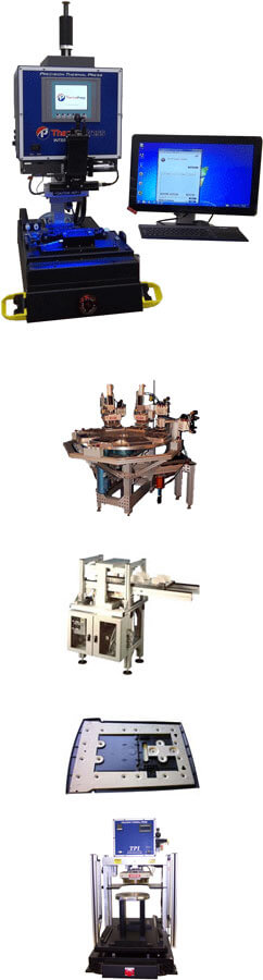
Assembly Equipment
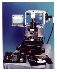 The thermal press required for the bonding process should be specifically designed for HSC assembly because of the precise controls that are required for successful bonding (Fig. 2). In addition to temperature control, the press must deliver precise, even pressure to the bond area. To accomplish this, the press must maintain planarity of the bonding blade to the part-holding fixture. Silicone rubber is often used on the bonding-blade/HSC interface to distribute the pressure evenly and to compensate for nonlinearities in the blade surface. The use of silicone rubber requires higher blade temperature and longer dwell times. The silicone rubber also deteriorates during the bonding process and requires continual replacing. If not monitored closely it can cause poor-quality bonds. The need for silicone rubber in the process can be eliminated if the components, part-holding fixture, and bonding blade meet stringent dimensional tolerances to assure the even application of pressure. Elimination of the silicone rubber allows for a dramatically shorter bonding-process dwell time and a lower bond failure rate.
Failures can occur in the assembly process for a number of reasons:
- If the surfaces to be bonded are not clean, smooth, and level they can affect the bond continuity and strength.
- The adhesive utilized on HSCs has a shelf-life, so particular attention must be paid to the manufacturing date of the connector. Typical shelf-life is 3-6 months; the connectors should not be used after their expiration date.
Heat-seal connectors offer many advantages over other connectors: they also have limitations.
- If bonding to a PCB, the pad height above the board should be kept to a minimum.
- Connectors are susceptible to an increase in contact resistance if they are subjected to a combination of high heat and humidity.
- If misassembled or damaged, the connectors cannot be repaired. They must be removed from the components, which can be cleaned and reused.
The HSC offers a unique alternative to other connectors because of its flexibility and its availability with fine-pitch traces. The HSC has allowed designers to create FPD containing products without the constraints common to elastomeric connectors. For PCB-to-PCB connections, the HSC offers a low-cost alternative for flexible-connector requirements.
Display-to-driver connections in the future will focus on a single flex circuit TAB that will be bonded to a display having all driver chips mounted on its perimeter. More than one display manufacturer is investigating this concept for flat-panel-display assembly, but the technology has not been perfected.
Contact Us for more information
Dan Fritschen (Sales Engineer -Young Technology, Inc.)
Monte McGrew (Sales Engineer – Shin-Etsu Polymer)